
Last Update: 2011-07-23
Home
Synth & Music
FPGA Experiments
Initially I've had my sights set on the larger boards with memory and LCD. Then the AvnetSP3A-EVAL400 devboard came along at just €50, was available without me having to pretend I'm a company at Trenz Electronic and that settled the issue. Some peripherals would still be necessary, but Digilent and it's Pmod catalog had already solved that problem, so I simply spent some of the budget on those. Another nice touch is that there is no need for an external power supply until you really hot-rod it: for all the stuff I've tried so far powering the board through USB was sufficient.
The S3A eval kit must have been too popular or something, because it has already been discontinued by Avnet. There currently isn't anything in this price range, unfortunately. Avnet now offers two Spartan6 development boards as an apparent replacement.
My choice of Pmod peripherals was natural also because there already were two Pmod extension connectors on the board. I really wanted to connect more than two and a quick look at the schematics showed that the SPI header was Pmod compatible, too. So the plan was to put the LCD on that header, unfortunately it turns out that the SPI header can't be used from the FPGA as it is under control of the PSoC. How about moving it to I²C, then? Good idea, only that header is not Pmod compatible and I'd have to re-program the I²C address of the LCD first because it's standard address is already taken by the I²C temperature sensor on the development board.
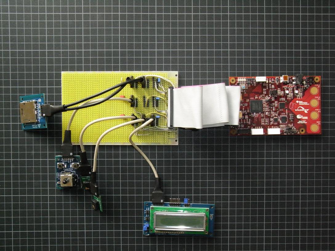
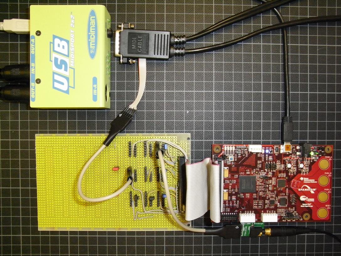
Surely, I could plug a Pmod into the 40-pin expansion header? Wrong again, the row from pin 1 can't be used since 3.3V and Gnd are swapped w.r.t. the Pmod pinout and the two rows on the other end of the connector provide Gnd along with four signals in the correct order, but there is no 3.3V in any nearby location. So the plan became to just pull apart a broken IDE cable I had lying around, pull quadruples of wires from it and splice in Gnd and 3.3V as necessary. I quickly realized that this would become messy and I hadn't the parts around to do it anyway. A few days later I found a very cheap stripboard at an electronics store I had visited to get some measurement cables and the new plan became to leave the IDE cable alone, solder headers onto the board and connect those with flatband cable.
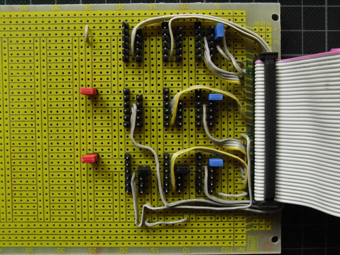
Luckily I found out early enough why this stripboard had been so cheap: the top print doesn't match the traces on the bottom in a few important places, so I had to be extra careful while soldering. I've also installed a few jumpers that allow to connect a different Gnd (the blue ones) and supply (the red ones) to two rows of headers, should this ever become necessary. Also, nine PMod headers need 36 signals, but only 35 are provided on the board, so the last one can't be fully independent. I decided to connect pin 4 of two headers (the black jumpers make or break that connection), so two SPI devices can share their clock line on those two headers. Each signal is available on a second header to be able to hook up probes.
The straight headers don't work too well with some of the peripherals (at least with the standard length cables, so I will later install four receptables along the end of the board with the standard double-wide spacing (three empty holes inbetween connectors). This will allow to plug the two the I²S Audio-DAC, the LCD and the Amp1 directly into the breakout board, which should reduce the cable mess considerably.
Pin 1: MCLK
Pin 2: LRCLK
Pin 3: SCLK
Pin 4: SDATA
Pin 5: GND
Pin 6: VCC
Next thing on the list was a MIDI interface, which I also wanted to put on the breakout board. I didn't have all the parts required, but I remembered I still have that PC MIDI cable for the SoundBlaster Gameport from my very first PC… so it turned out that the housing was easily pried open, the circuit was done with transistors rather than IC and that it would probably work well enough with 3.3V instead of 5V. Half an hour later I had added a Pmod connector to the MIDI cable and another ten minutes later a simple loopback connection from input to output was added to the FPGA sources. That worked, but produced errors with large sysex data for the loopback test in SoundDiver. Looks like the lower supply voltage does take it's toll somewhere, but I've added a de-glitcher to the FPGA code (I'll only switch the output when the input has been stable for 16 clocks at 16 MHz) and now have a nice stable MIDI interface into the FPGA.