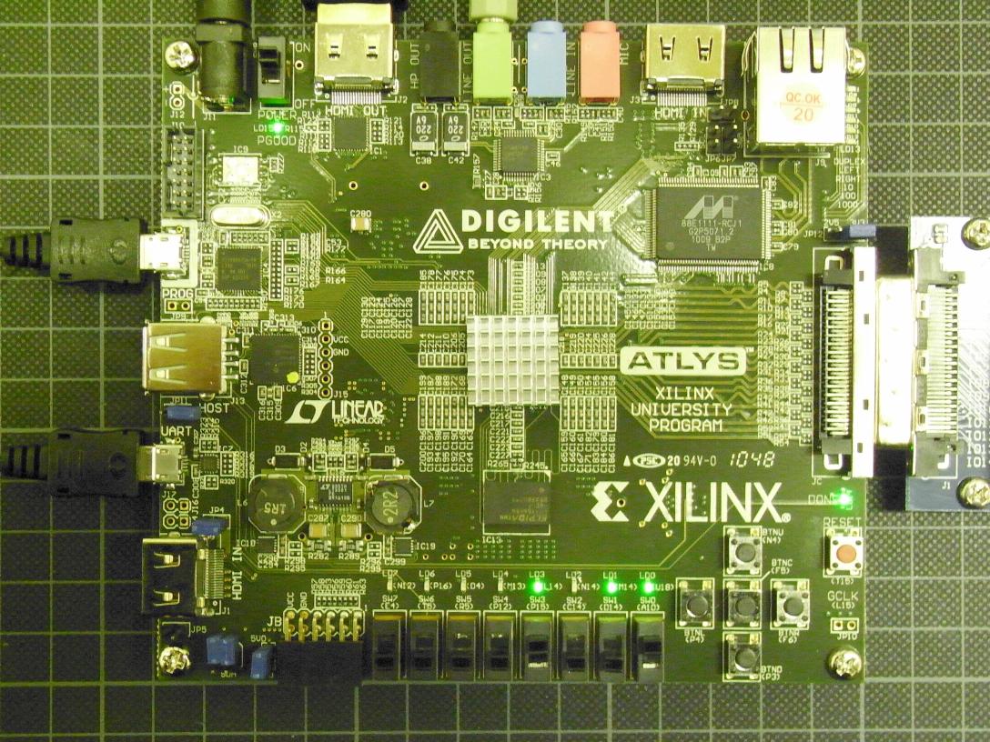
Development Board 2 — Digilent ATLYS Spartan6
The Digilent ATLYS is the current winner in the
bang-for-buck category: the S6LX45 is the second largest part that
the free WebPack edition will handle, it has AC'97 audio I/O, HDMI
video I/O (you'll have to handle those with the FPGA, so officially
no FullHD at 60Hz), comes with 128 MiBx16 DDR2-DRAM and 8 MiB QSPI
Flash, tri-mode ethernet, USB UART and HID and a few assorted
on-board LED, buttons and switches. Programming is via a built-in
USB port, so no extra JTAG gear needed. External PSU is mandatory
however, as the larger FPGA and additional on-board stuff take their
toll.
Aquired again from Trenz Electronic.
- HDMI output
- I've modified the design
from Xilinx XAPP495
to check which output modes I would get working. Standard FullHD
does work even if not officially supported, I've even produced
modes with pixel clocks up to 193 MHz, more than twice the maximum
frequency in the datasheet (my largest monitor just switches off
when it gets higher frequencies), but the pixel pipe is slower
than that and you get some flickering pixels. WUXGA (1920x1200)
is working stable with reduced blanking (128 MHz @ 50 Hz /
154 MHz @ 60 Hz). A 1080p50 mode with reduced blanking gets the
pixel clock to 115MHz, which is almost within the datasheet spec,
but not all monitors (and even fewer TV) recognize that mode.
Notes on ATLYS board
I'm still trying to wrap my head around this board, a few things to note:
- USB HID input:
- The HID interface controller does currently not support USB
hubs and so you can only connect a single USB device. It does
however correctly recognize combo devices that present both a
keyboard and mouse as two different USB endpoints and converts
them into two emulated PS/2 ports. Devices I've confirmed to
work include
the Cherry G80 Touchboard and probably most USB
wireless desktop combos.
- Most keyboards will work straight away, but the mouse will
just announce its presence and then fall silent until it is
explicitly reset from the host side (exactly as mandated by the
PS/2 protocol). This means you do need write capability for
your controller if you want to use a mouse, but may skip this if
just using a keyboard (unless you want to control the LED or
change the translation map).
- The
current ATLYS reference manual has switched the clock
and data lines for the PS/2 mouse port: the correct association
is
P18 clock, N18 data. You need to
configure the IO on the PS/2 lines for pull-up, otherwise
nothing works.
- Older versions of
the ATLYS reference manual incorrectly stated the
PS/2 clock would be 30kHz. It actually runs at a
standard-conforming 15kHz. The error has been corrected in the
latest version of the manual in one place, but later a reference
to the incorrect clock remains (clock low/high time has
apparently been mistaken for clock period in calculating the
figure).
- The
current ATLYS reference manual states that you can
connect a USB stick with a single bitfile in the root directory
to the HID port and the HID controller then configures the FPGA
if the mode jumper JP11/HOST is closed. I have not had much
luck with that until very recently, but I think I finally found
why just one of my many different USB sticks works: If the
USB device claims it is bus powered and also a maximum current
larger than 100mA, then it is not enumerated by the controller
on the Atlys board and does not work. Funnily, if it
claims to be self-powered it works even when it pulls much more
than those 100mA from the USB port, otherwise the harddisk
enclosures wouldn't work. The one USB stick that reports just
100 mA in its descriptor is a DeLock nano 1GB (just a tiny bit
larger than the USB receptable), so this works rather well — no
mechanical strain on the HID port of the Atlys. When it works,
be patient: loading the bitfile from USB is rather slow, it
takes slightly longer than half a minute.
- The ATLYS general UCF file seems to belong to an earlier
board revision that had an SPI interface for the USB HID controller.
Also it lacks information about the voltage domains of the IO banks.
The
data/system.ucf in
the demo project is correct (it also has the correct
association for the PS/2 ports). You should also set CONFIG
VCCAUX = "3.3" in the constraints.
- Installing the host jumper will result in LED7 (the leftmost)
being permanently lit. I don't know if there's a chance to damage
the FPGA if the bitfile configures an output to LED7, but it is better
not to try I guess.
- The tri-mode Ethernet physical requires the EDK, so you can't use
it directly with WebPack. Additionally, Marvell in their infinite
wisdom don't let you read their data sheet until you sign an NDA.
There are various efforts underway to get ethernet working without
using encumbered cores or datasheets, but so far I've not checked
any of them.
- The AC'97 sound initializes with all channels muted, so you need
to write a few registers before any data sent to it can be heard.
- My board came with the SDA/SCL next to the Pmod header jumpered
vertically (just like the photo on the product page). Looking at
the traces and the silkscreen labeling this actually shorts SDA/SCL
on the TMDS chip and the FPGA. While this shouldn't cause damage, I
don't think this is intended, I've opened both jumpers for now. The
correct jumper placement should be horizontal if a loop-through
between HDMI in and out is required.
- After installing the Digilent plugin in the appropriate place you
can use Impact to program the device via its USB port.
- ISE12
- You cannot re-load the project since that will crash
Impact. Digilent has informed me that's a bug in Impact that
Xilinx is aware of. Chipscope works just fine for configuring
the device.
- ISE13.1
- This bug has been fixed in ISE13.1 (you also need
to install a new version of the Digilent plugins to match). You
still can't double-click the »Configure Target Device« in ISE
since it runs Impact on a batch file that wants to set
a
port=auto on the programming cable. The Digilent
plugins support no such option and the device will not be
programmed. However you can start Impact through »Manage
Configuration Project« or run Impact in batch mode from the
command line (replace port=auto
with target=digilent_plugin).
- ISE13.2
- Finally the Digilent plugin is fully supported in
ISE and
port=auto works. There is a (new?) bug in
Impact however: when configuring the cable by hand Impact will
detect the maximum JTAG frequency as only 1 MHz for the JTAG HS1
and switch the cable back to that. In autodetect mode it happily
uses the default 10 MHz, while in batch mode you can set it to
30 MHz and it will switch down to 25 MHz, which it detects as
maximum JTAG speed (Chipscope uses the full 30MHz during
configuration).
- ISE13.3
- There have been no changes to the Digilent plugins
and the bug in Impact regarding the JTAG clock frequency is still
present..
- My original board developed a fault in the power supply and had to
be replaced. While I don't really know what happened, looking at
the schematics I noticed that one of the switching regulators on the
board, the LTC3546, is specified for a maximum input voltage of only
5.5 V (with an absolute maximum rating of 6 V). There is absolutely
no protection circuitry between the power input and that chip and
the power switch does not actually remove power from the board —
instead it just disables the switching regulators. This suggests
you should be very careful with the external power supply and unplug
it when the board is not in use.
Cray-1S
So, what does one do with that copious amount of logic? Re-build a
supercomputer icon, of course. Even better when a lot of the work
has already been done for you:
here's Chris Fenton's Homebrew Cray-1A project — and
he has just put the sources on
this Cray-1X
Google code SVN. The Verilog is nice and clean and it is
starting to work on the ATLYS board at 40 MHz currently (with some
inferred multipliers replaced by Coregen modules). I still hope
I'll get it to the original 80 MHz, but currently there's too much
routing delay in a handful of nets. If I can remove the longest few
paths I should be up to about 50 MHz and it will be an uphill battle
from there as there is apparently a great number of paths sitting
around in the 20 ns region.
The 160 MFLOPS of the Cray-1 isn't something that gets much notice
today. There's another aspect that made the Cray-1 the fabulous
supercomputer that it was at it's time: it sustained 640 MiB/s in
it's 4 MiW of main memory. This proved elusive for workstations,
let alone PC, for many more years, but should be possible to achieve
on the ATLYS board. The peak bandwidth of the DDR2-DRAM at 320 MHz
would be twice as good as needed (so the interface could even be
timeshared with some IO), but there seems to be no way to get to the
data within a fixed 11 clock periods latency (137.5 ns at 80 MHz
clock) unless I figure out how to keep the memory interface from
inserting refresh cycles on its own. The memory and indeed all
functional units of the Cray-1 always complete a request in a fixed
number of cycles once it has been issued, so accomodating a variable
latency requires changing the architecture or stopping the clock
(both of which would require extensive changes to the current code).
The project has not been progressing as well as I had hoped at
first, but I've been reading up on the Cray Hardware Reference
Manual [PDF 19MiB], which has lots and lots of detail that
are slowly beginning to make sense to me.
